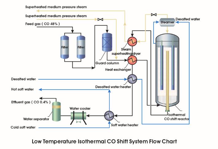
For shift processes with high feed CO content (45% to 85%) and/or high CO conversion requirements, Anchun’s isothermal CO shift technology offers superior applicability over conventional adiabatic CO shift technology.
- Lower Operational Cost
- Catalyst sintering avoided; Reaction temperature can be set with isothermal condition ; Catalyst lifetime extended due to mild reaction condition
- Evolved reaction heat used for medium pressure steam production.
- High CO conversion due to low reaction temperature.
- Lesser Capital Investment
- Lesser land-use requirement due to reduced number of reactors and simplified process design
- Lesser equipment investment due to the single-reactor system
- Easy to Operate
- Reaction temperature can be set by adjusting one single steam pressure valve
- Reaction temperature can be easily set with isothermal condition with very minimal variation ; Operational simplicity lowers the training requirement on the operator
Anchun continues to commit relentless efforts in integrating complex mathematical modeling, rigorous experimentation and endless improvements in manufacturing craftsmanship and customer service.
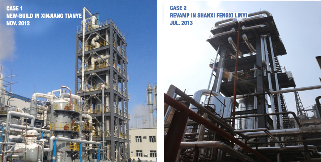
Each new-build and revamp system shows that:
| Item | Case 1 (New-build) | Case 2 (Re-vamp) |
|---|---|---|
| Plant Site | Xinjiang Tianye Group, China | Shanxi FengxiLinyi Group, China |
| Start-up Date | Nov.2012 | Jul.2013 |
| Upstream Process | Calcium carbide process | Coal gasification |
| Downstream Process | ethylene glycol production | Ammonia production |
| Shift Reactor Feed Pressure | 1.75MPa | 3.34 MPa |
| Shift Reactor Pressure Drop | 0.010MPa | 0.024MPa |
| Shift Process Feed CO Content (vol%) | 80% | 48% |
| Shift Process Effluent CO Content (vol%) | 17% | 0.6% |
| CO Conversion | 67% | 98% |
| Pressure of Produced Steam from the Reactor | 2.2MPa | 3.7MPa |
| Steam Production Capacity of the Reactor | 7.2 t/h | 12.0 t/h |
| Reactor Feed Gas Temperature | 210℃ | 250℃ |
| Catalyst Bed Temperature Variation | Axial and Radial ± 2℃ | Radial ± 2℃ |
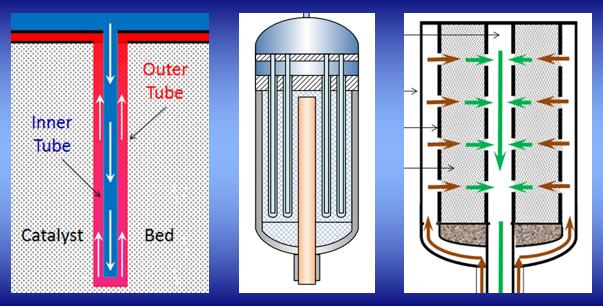
The middle graph is a simplified structural illustration of this reactor, consisting of the outside pressure vessel, the inside catalyst basket, the central gas pipe, the water chamber, the steam chamber and the water tube sets distributed in the catalyst bed.
The left-hand side graph illustrates the water-steam circulation. Cooling water comes from the steamer, enters the water chamber located at the top of the reactor and runs downwards in each inner tube. The heat generated from the catalyst bed heats up the water indirectly. The produced steam runs upwards in each outer tube and rises up to the steam chamber located right under the water chamber.
The right-hand side graph illustrates the gas flow direction in the reactor. The feed gas mixture enters the isothermal CO shift reactor inlet located at the bottom; then runs upward into the annulus between the outside vessel and the inside catalyst basket, through the perforated catalyst basket; radially from outside in; the reacted gas mixture travels in the central gas pipe and exits from the bottom of the reactor.
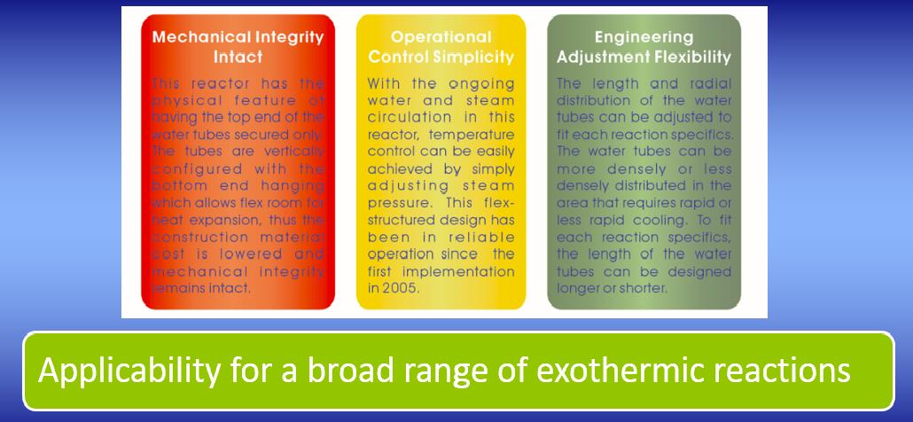
- Mechanical Integrity Intact
This reactor has the physical feature of having the top end of the water tubes secured only. The tubes are vertically configured with the bottom end hanging which allows flex room for heat expansion, thus the construction material cost is lowered and mechanical integrity remains intact. - Operational Control Simplicity
With the ongoing water and steam circulation in this reactor, temperature control can be easily achieved by simply adjusting steam pressure. This flex-structured design has been in reliable operation since the first implementation in 2005. - Engineering Adjustment Flexibility
The length and radial distribution of the water tubes can be adjusted to fit each reaction specifics. The water tubes can be more densely or less densely distributed in the area that requires rapid or less rapid cooling. To fit each reaction specifics, the length of the water tubes can be designed longer or shorter.